3v To 5v Boost Converter Circuit Diagram
Lm2577 boost converter circuit 3v to 5v 1a boost converter circuit diagram Converter resistor capacitor
3v To 5v 1a Boost Converter Circuit Diagram
How to build a dc-to-dc boost converter circuit 3v to 12v converter circuit diagram Best 3.7v to 5v boost converter circuit & module
Buck boost regulator circuit design using xl with free nude porn
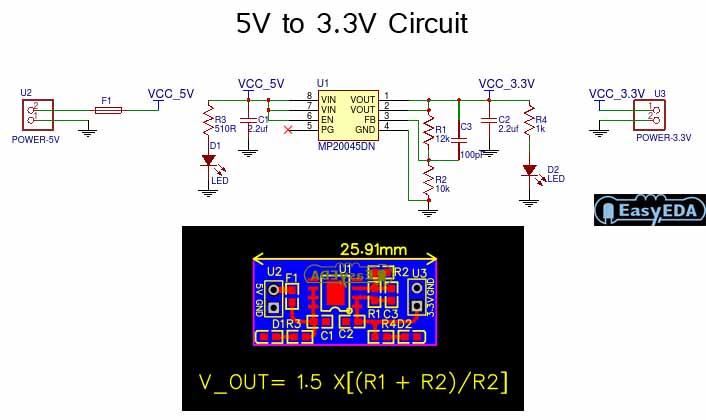
5v to 3.3 v schematicBoost converter circuit diagram Converter breadboard inductorBoost converter circuit 555.
5v to 12v boost converter circuit diagramConverter diode schottky capacitor 3v to 12v boost converter circuit diagram3.7v to 5v boost/step-up dc converter circuit.

5v to 12v boost converter circuit diagram
3v to 12v converter circuit diagramブランド 12v voltage regulator power supply for coal mining aerospace 1a 3v to 5v boost converter circuit diagramBoost converter circuit.
3.7v to 5v boost converter using me2108 icConverter circuit diagram 3v to 5v boost circuit for battery charging and led driver applicationsCreative inventor 유튜브 채널 분석 보고서.

Boost converter circuit using mc34063 ic
3v to 12v boost converter circuit diagramConverter 5v 15v circuit lm2577 7v diagram 12v regulator datasheet Easy boost converter circuits explained homemade circuit, 41% off5v boost converter module circuit diagram.
To 5v boost converter circuit diagram using mc34063, 55% off3.7v to 5v boost converter me2108a33p 5v circuit led battery 3v boost driver charging applications3v to 5v 1a boost converter circuit diagram.

3v to 12v boost converter circuit diagram
3.7v to 5v boost converter circuit diagramConverter circuit diagram Boost converter schematic555 boost converter circuit ic components timer using transistor bc547 capacitor npn required theorycircuit.
3v to 5v 1a boost converter circuit diagramBoost converter 3v to 5v boost converter circuit diagram.