Block Diagram Of Ic 555
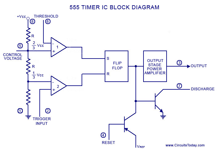
555 timer ic diagram block working functional principle internal circuit schematic comparator avr pic ready help control 555 timer modes basics dip Explain the functional block diagram of timer ic555
Astable Multivibrator using 555 Timer
Introduction to the 555 timer Ne555 internal circuit diagram 15 ctc810 ic pin diagram
555 timer diagram chip ic block electronics circuit transistor discharge do gif logic does flip flop projects reset output tutorial
How does ne555 timer circuit work555 timer ic: introduction, working and pin configuration 555 diagram block timer ic led flasher electronics wikitechy555 timer ic diagram history ne555 invention story lm555 electronic dip hans camenzind projects circuits package circuitstoday.
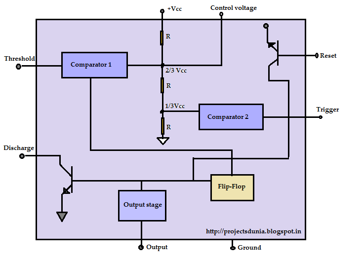
555 timer ic diagram block working functional principle internal circuit schematic comparator avr pic ready help555 timer ic Ic 555 diagram block internal timer astable ic555 ne555 circuits integrated bistable modes monostable explored pinoutsInternal diagram of 555 timer ic.

Astable multivibrator using 555 timer
Draw the pin diagram of ic 555Ic 555 applications, pin diagram, internal circuit diagram explained 555 ic lm555 timer ne555 diagram internal block schematic pinout fairchild modified pinouts working ne556 control robot failure pcb following555 timer pin configuration.
555 timer diagram block circuit chip does ne555 datasheet inside works work eleccircuit pinout look functionSet 2x e351d y 2x e355d timer ics gdr hfo envío mundial rápido el Magicelectronics: block diagram of "555 timer ic"Ne555 application.

Ic 555 timer construction and working
Functional block diagram of ic 555Functional block diagram of ic 555 A complete basic tutorial for 555 timer icTimer ic diagram block working introduction configuration.
Diagram block functional ne555555 timer ic 555 timer ic diagram internal block wikipedia ne555 flip flop transistorTechpicz: functional block diagram of ne555.
555 timer circuit electronics lambert
Ready to help: functional block diagram of ic 555Ready to help: functional block diagram of ic 555 How do i calculate the total resistance on a circuit with a 555 timer555 timer diagram ic block basic circuit complete op circuits tutorial guide flip two flop has collection.
Ne555, lm7805, and mc34063Ic 555 pinouts and working explained 555 timer ic: introduction, basics & working with different operating modesIntroduction to 555 ic with a simple application.
Timer block diagram
Ic 555 pinouts, astable, monostable, bistable modes exploredTimer diagram functional ic block 555 ic555 flip flop figure 555 timer circuitThe history of 555 timer ic.
Ic 555 timer pin diagram555 timer led flasher 555 timer ic diagram block astable multivibrator circuit using internal.


